
Note: Thanks for so many compliments and suggestions for this guide over the past few years. Many of the more interesting questions appear at the bottom of this article, but I am finding it hard to keep up so have had to close off the comments feature.
Please ask questions or make suggestions through the P38 Forum at aulro.com (aimed at us Aussies) or rangerovers.net (rest of the blue marble) so that a wider audience of P38 owners may benefit from your questions and suggestions.
Preamble and Introduction
The EAS (Electronic Air Suspension) Valve Block is one of those many, many things that Land Rover will charge you a small fortune to replace. A major cause of problems associated with the valve block is the o-rings wearing out. Fortunately these can be replaced fairly easily and cheaply.
What Land Rover doesn’t tell you in the manual, and most independent workshops don’t know, is that the EAS Valve Block and Compressor should be treated as a 1-2 year maintenance item. Instead they get neglected, and when something fails these absolutely brilliant vehicles get branded as unreliable. Of course it doesn’t help that even a small failure in the EAS will usually lead to the car sitting on the bump stops. From an owner’s view point, all the more reason to know what needs to be done, and how often to do it.
When I did my first EAS Valve Block rebuild a few years ago, it seemed there must be a leak from inside the EAS Valve Block as I could not detect any external leaks using the “soapy water” spray method. This was in the days before I owned HardRange.com and had plenty of my own EAS O-rings Kits to play with, so I purchased a kit and after-market Diaphragm from Dennis at Rover Renovations (sadly, no longer in business).
The instructions at RangeRovers.net were an inspiration for me, but I found them a bit lacking for keen amateurs such as myself. I took lots of photos so I could remember how to put things back together again. I then put some words around selected photos and created this page to share with others.
The first version of this article was well received by other P38 enthusiasts at AULRO.com and RangeRovers.net so it seemed like a good idea to maintain it with more information, better photos, and input from other P38 enthusiasts.
I make no apologies that my EAS system looks a little different than most, as I run an air-locker regulator, on-board air kit, and EAS Emergency Bypass Kit. My basic EAS setup is the same as standard, however you may see a few extra tee-pieces and air lines when browsing through my photos below.
A PDF version of this page is available for off-line viewing and printing.
The PDF version may not be as current as this page.
Preparation
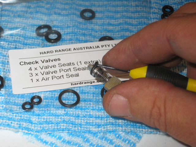
A complete set of o-rings for the valve block from your preferred supplier, such as Hard Range.
A diagnostics tool such as EAS Unlock Suite , Nanocom Evolution or FaultMate to de-pressurise the EAS and then to test it afterwards.
Assortment of spanners, screwdrivers, pliers, cleaning fluids and rags.
A small crotchet needle, brass wire or brazing rod to remove the o-rings.
A few hours to spare, plenty of coffee/tea and suitable background music… .
Study the diagram below to get a basic understanding of the flows in/out and inside the valve block. It may also help with troubleshooting issues before and after the procedure.
At the right side of the diagram is a representation of the wiring to each solenoid. This should be handy if you forget to mark the solenoids before removing them.
A PDF version of this diagram is available.
Cleaning the removed bits and pieces
I just used a clean rag sprayed with a bit of WD-40 to wipe the block parts down until they looked shiny again. Some folks reckon that cleaning the block with soapy water and letting it dry slowly in a warm (not hot) oven also works.
For the airways, I used a can of computer keyboard compressed air to blow out any dust and WD-40 residue.
For the plastic case, you can’t go past Windex (or similar) glass cleaner in my view. I didn’t worry about trying to make the plastic bits too clean as they are just going to get filthy again real soon.
Removing the EAS unit
De-pressurise the EAS system using your tool of choice. I really like the EAS Unlock Suite from Storey Wilson.
If you have an EAS Emergency Bypass Kit (EBK) fitted, you can purge the last bit of air in the system through the inflation valves.
You may elect to be extra safe, and remove the valve stems so there is no way that pressure can build up in the system.
IMPORTANT: after de-pressurising the EAS, leave the ignition switched off until you finish this procedure and have reconnected the electrics. Otherwise you are likely to generate an EAS “Hard Fault” which you will need to clear with a diagnostics tool or by a dealer.
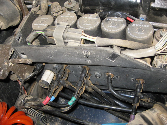
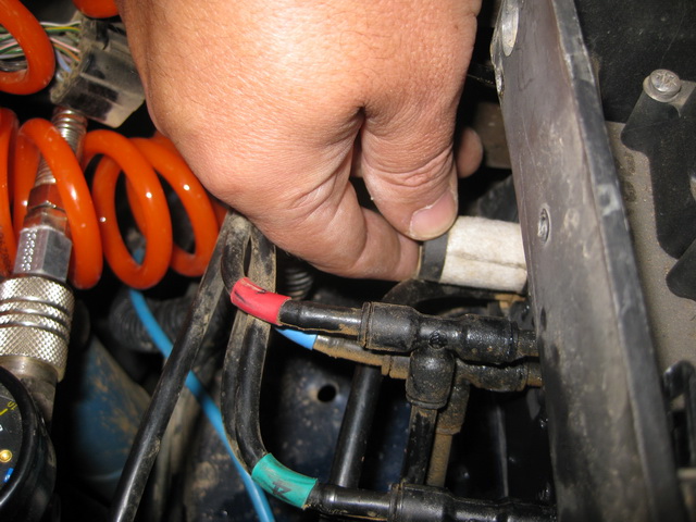
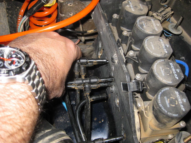
The next photo shows the air line connections to the EAS box. If you don’t have an EBK fitted, ignore the tee-pieces.
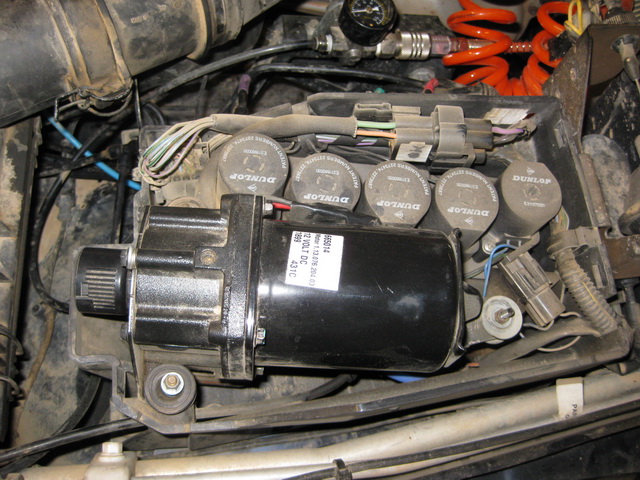
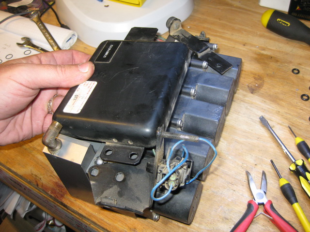
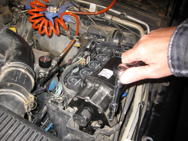
A top view of the EAS housing with the cover removed. Never mind that I’ve got an over-sized air compressor in mine, the process is the same for a regular unit.
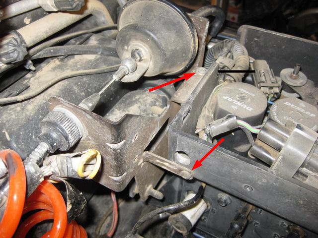
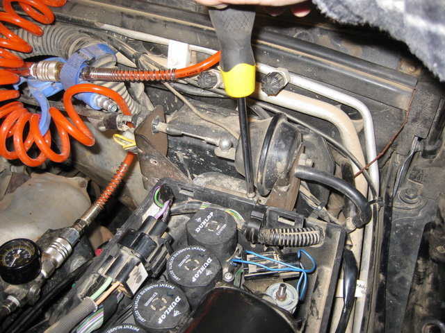
Location of the two screws that secure the Cruise Control unit. You need to remove these to get easy access to the bolt at the rear of the EAS that holds the valve block and driver unit in place.
Remove the three nuts holding the compressor in place. If these three nuts have been over-tightened before, a bit of WD-40 will help to loosen them. If it is still tight, use a set of pinch-nosed pliers to hold the metal collar of the vibration mount while you unscrew the nut.
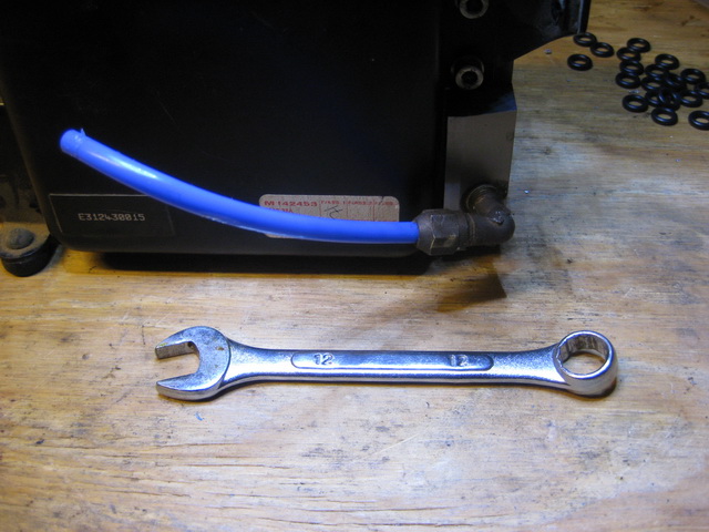
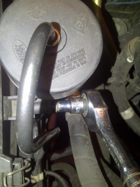
Lift the compressor a little to get access to the air line below. Use a 12mm spanner to undo the brass olive nut holding the air line in place.
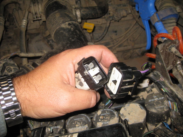
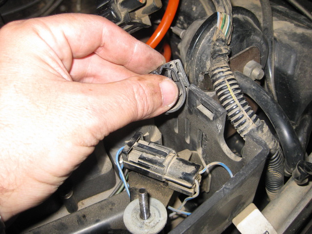
Disconnect the compressor wiring harness from the casing, and then disconnect the multi-plug.
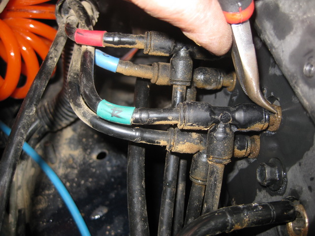
With the compressor removed. Ignore the tee-piece on the air line in the photo below, it is part of my custom setup.
Use a flat blade screwdriver to unclip the wiring harness from the casing.
Slide the retaining clip to the side to release the wiring loom.
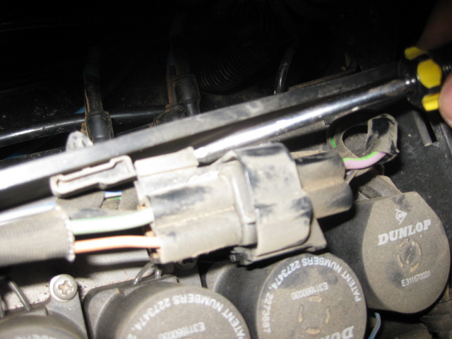
Remove the second retaining clip and unplug the wiring connectors.
Unscrew the exhaust valve filter/silencer and put aside.
Use a screwdriver or needle-nose pliers to depress the collets on the airlines going in to the housing and pull out the air lines.
I should advise you to label each of the air lines so you know which one goes where. However, I found that mine line up pretty well with the case and not much guesswork is involved.
It is advisable to cap off the exposed air lines to prevent dust and moisture entering.
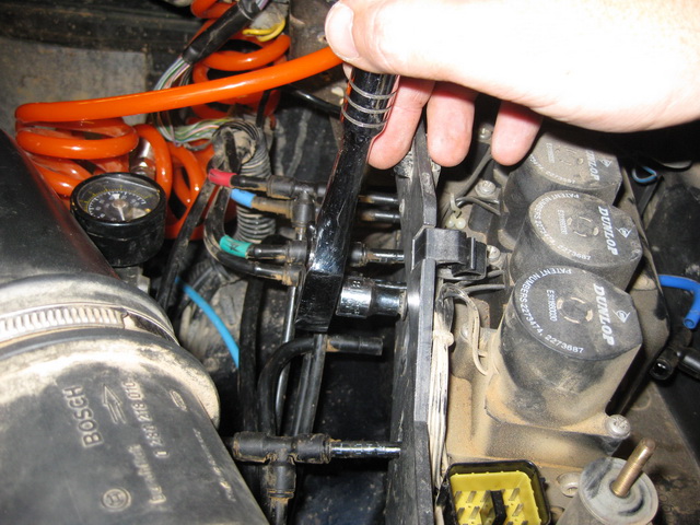
The picture below with the air lines pulled aside gives better visibility of two (out of 3) bolts that hold the valve block in place.
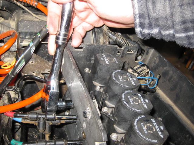
Use an 8mm socket or spanner to remove the two bolts on the air line side of the housing, and another bolt at the rear near the cruise control unit.
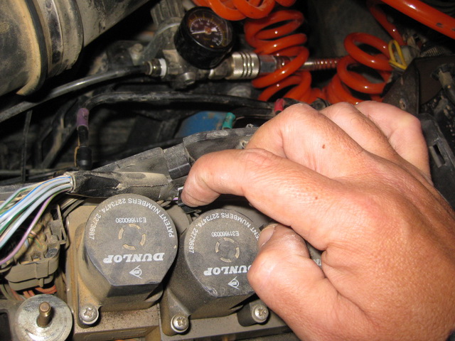
Remove the two cable clips on the side of the case to make it easier to remove the valve block. A flat screwdriver blade or fingernail at the back of the clips will help them pop right off.
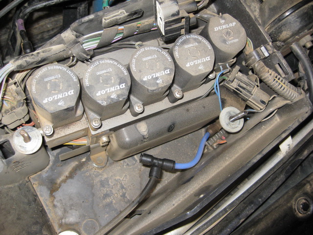
With the clips removed, three bolts removed and wiring connectors disconnected, the valve block and driver unit should slide straight out.
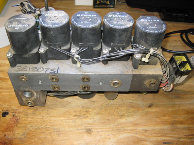
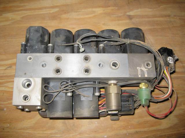
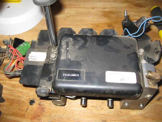
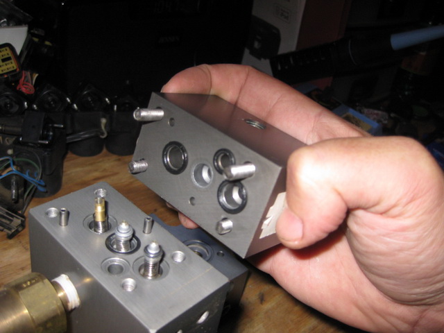
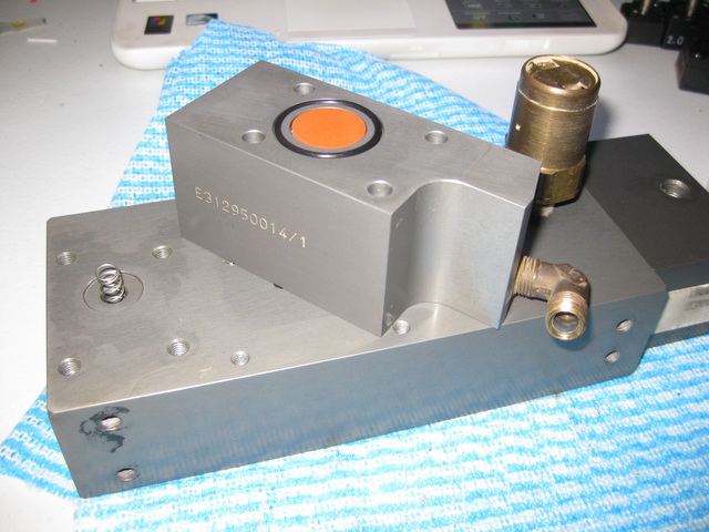
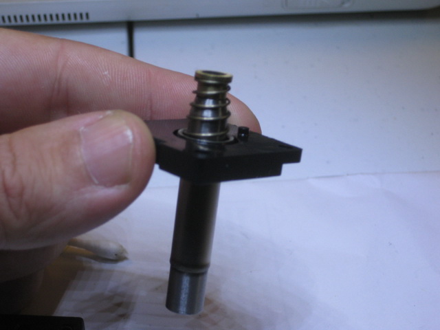
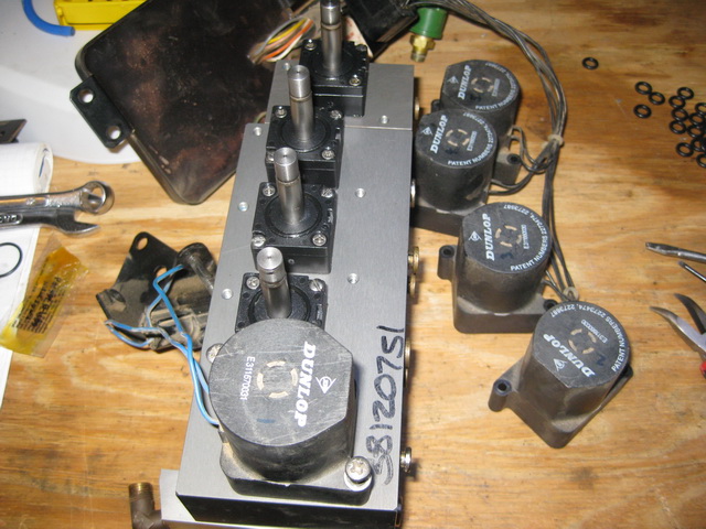
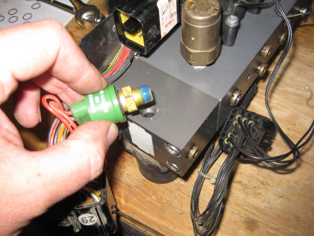
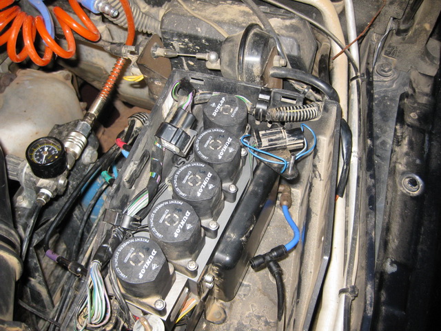
The removed unit on the bench ready for further disassembly.
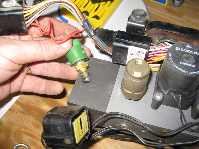
The brass fitting is the pressure relief valve. The green one is the pressure switch.
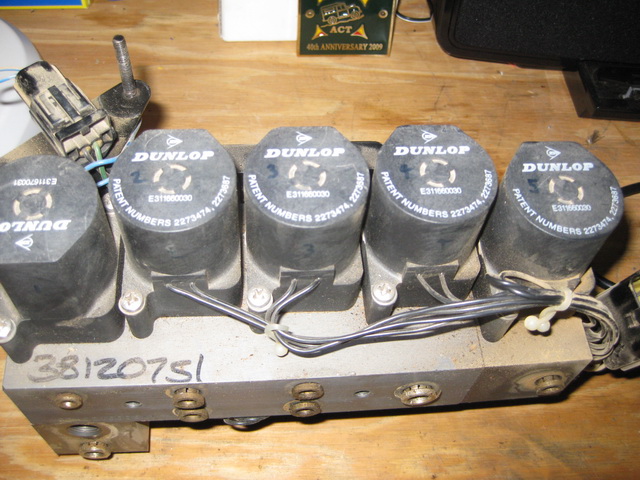
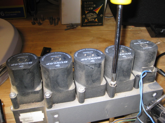
I DO RECOMMEND numbering the solenoid covers so you remember which one goes where. If you get mixed up, use the diagram at the beginning of this guide to work it out.
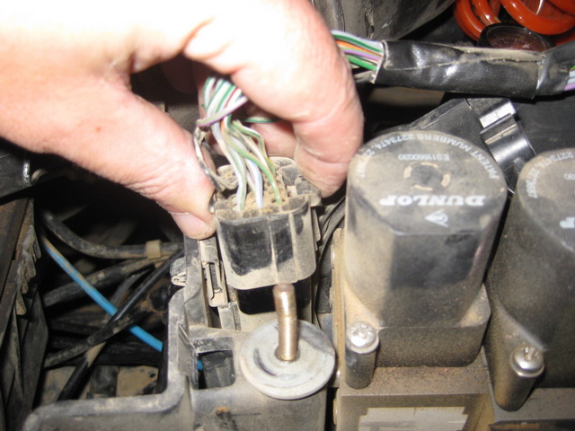
Remove the wiring loom/connector from the bottom of the unit.
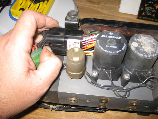
Use a 14mm spanner to unscrew the pressure switch (optional).
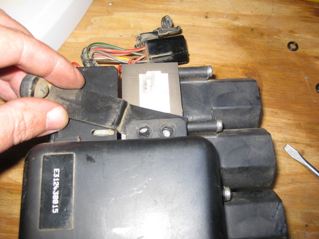
Remove the driver unit by undoing the four Allen key bolts, and disconnect the plug with the blue wires to it.
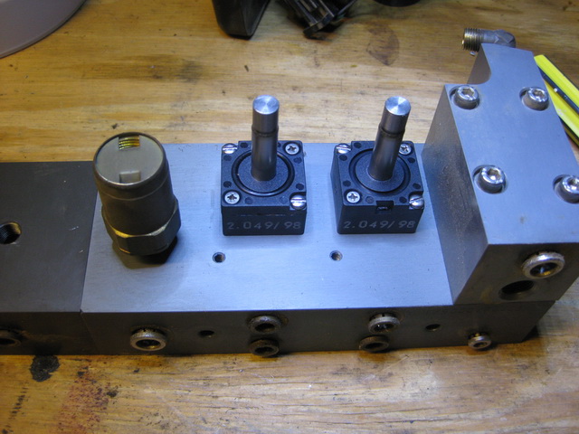
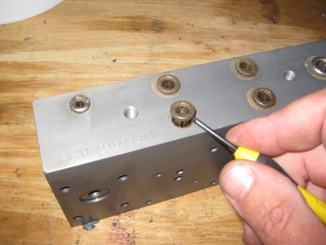
Noting the orientation of the solenoid covers, remove the five on top and two underneath the block.
Note the orientation of the solenoid bases for re-installation, and the small Diaphragm Solenoid at the right.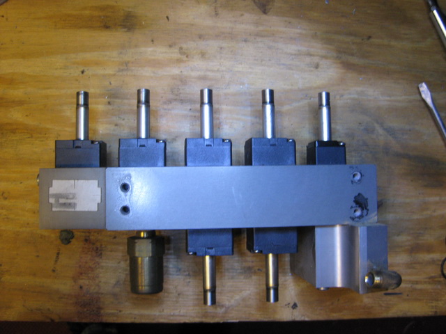
The solenoid bases are held in by two screws each. On my 1999 P38 these are flat head screws, but on my 2000 P38 they are Phillips head.
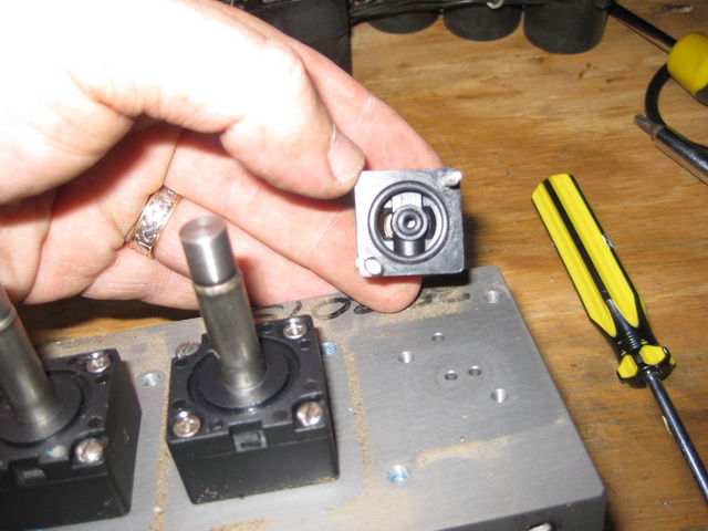
Remove each of the solenoids and place them with their corresponding covers for safe-keeping. Alternatively, number them as you did for the solenoid covers.

As you remove each solenoid base, note the two o-rings underneath.
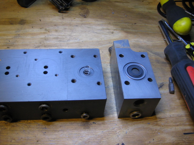
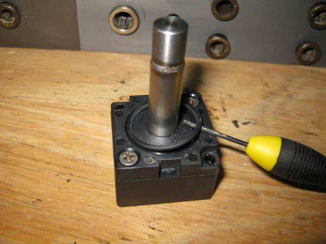
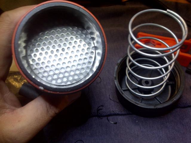
Turn the block over to remove the final two solenoids, and the four Allen-head bolts that hold the diaphragm block in place.
The inlet solenoid and diaphragm block removed. Don’t lose that spring.
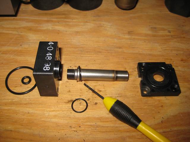
Remove the old diaphragm and o-ring from the diaphragm block.
Gently remove the metal cap from the diaphragm.
NOTE:
If you are replacing the original diaphragm with the “orange disc” diaphragm from Hard Range, you will be substituting both the metal cap and the rubber diaphragm with the single orange disc.
The spring from the original diaphragm is re-used with the “orange disc” diaphragm.
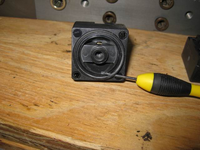
At the other end of the valve block, remove the four Allen head bolts.
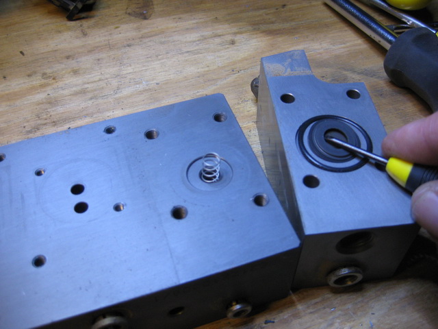
Carefully remove the block to reveal the Non-Return Valves (NRV). Note the orientation of the NRV’s for reassembly.
Remove the NRV’s and o-rings.
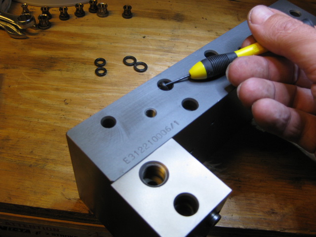
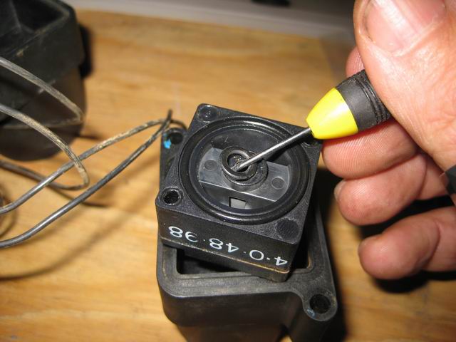
Turning the block on its side, prise out each of the collets with a small flat screwdriver blade.
Fish out the two o-rings from each of the holes that the collets were in (for the keen-eyed… the photo below was taken after the Diaphragm/inlet block was replaced).
Thanks to Hoges and Robsrod_58 at AULRO.com for their recommendation to use a small crochet needle, length of 2mm brass wire or brazing rod (end flattened, slightly rounded and polished) instead of a screwdriver to fish out the o-rings. The logic behind this is that the screwdriver is harder than the block and may damage or score the hole.
Replacing the o-rings
The o-ring kit should more than enough o-rings to replace all the o-rings in your valve block, plus a few extras in case you make a mistake.
Generally, it is a good idea to coat the o-rings with o-ring lube or some Vaseline to assist in sealing.
The order of replacement is up to you. This is how I did mine.
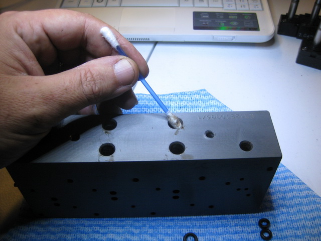
Before inserting the new o-rings, give each of the holes a good clean and remove any dirt and residue with a cotton bud or other clean material.
Starting at the Non-Return Valve (NRV) end of the block, replace the o-rings on the NRV’s. Use a small flat head screwdriver to remove the old o-ring and slide the new ones in place (Bag D in the Hard Range kit).
NRV’s reinstalled with new o-rings. To avoid any binding of the NRV’s, do not lubricate the o-rings on the NRV “cones”.
Replace the NRV block and tighten the bolts.
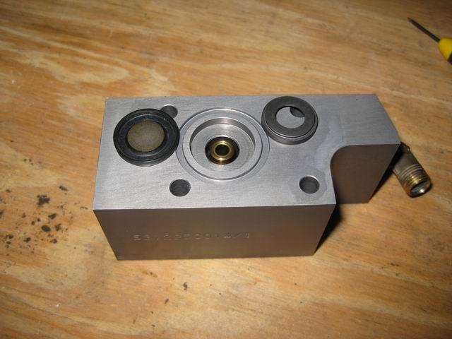
Go to the other end of the block and replace the o-ring around the diaphragm recess (Bag A in the Hard Range kit).
If you are using the original diaphragm, the photo below shows new o-ring inserted with a touch of lube to aide in sealing. Remember to replace the spring (not shown in the photo below).
If you use the “disc” diaphragm from Hard Range, shown below, discard the old diaphragm but keep the spring and replace the seal as shown below.
Reattach the block and secure with the four Allen-head bolts. Tighten diagonally opposite corners alternately.
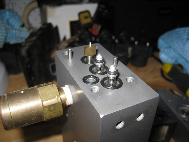
Next, insert the o-rings in to the air line holes. Each hole will take two o-rings to give a good seal (Bags E and F in the Hard Range kit).
It is pretty obvious which holes takes the 4mm, 6mm and 8mm o-rings. Remember to lube them well before inserting, as this is where the majority of nuisance leaks occur.
A top tip from Shadow Keeper at RangeRovers.net:
“When I re-built mine I kept finding that the air-line keeper o-rings kept folding when I tried to seat them in the valve block. I ended up using the blunt end of a drill bit (can’t remember if it was an 8mm or 6mm) and pushed them in that way, it really did the job.”
Good advice, and it worked well for me too. An 8mm ( or a 3/8″) drill bit for the 6mm o-rings, and a 12mm bit for the 8mm o-rings, did a good job of seating them in the holes.
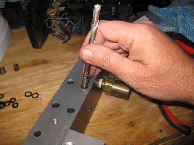
With the o-rings sitting properly in the holes, push the collets back in and check the pathway is clear by pushing a smaller drill bit through the hole, i.e. a 5mm drill bit though a 6mm hole, etc.
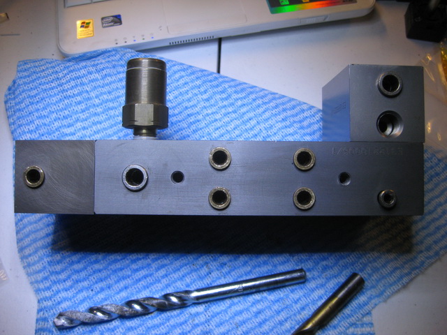
The photo below shows the valve block with o-rings and collets inserted. By inspecting the photo closely, you can easily see where the 4mm, 6mm and 8mm o-rings are located, or refer to the diagram at the beginning of this guide. Hint: there are 5x 6mm, 2x 8mm and 1x 4mm collets.
Disassemble each solenoid one at a time, being careful to remember which goes where.
The air spring solenoids are interchangeable with each other.
The exhaust and inlet solenoids are also interchangeable with each other.
The diaphragm solenoid is unique.
Air spring and inlet/exhaust solenoids should not be mixed. If you are unsure, refer to the diagram at the beginning of this guide which shows the type of solenoid by plunger type.
Inlet/exhaust valve solenoid/plunger shown below, identified by the large rubber foot..
A common cause of leaks on the solenoid valve stem is a worn or crushed o-ring. when replacing the thin o-ring on the stem (Bag C in the Hard Range kit) turn it upside down as shown below, and rotate the stem to ensure it sits flush.
Air spring plunger shown below, identified by the tapered plunger body and rubber inside the brass ring.
Reassemble the solenoid body, then replace the top and bottom o-rings for each of the solenoid valves (Bags A, B and C in the Hard Range kit). A little lube helps to seat and seal it.
Note: the small solenoid for the Diaphragm does not have a top o-ring.
 Don’t forget to replace the bottom inner o-ring.
Replace the solenoids in the same orientation and position as you removed them. Top view.
… and bottom.
Replace the driver unit and reconnect the multi-plug with the blue wires.
Note how the footing locates under the bracket.
Replace the pressure switch if you removed it. I applied a dab of Loctite thread sealant to keep it sealed.
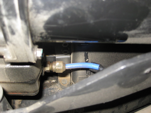
Reattach the air line olive with a 12mm spanner.
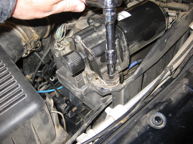
Place the block back in the housing and secure with the three bolts… two at the air lines side and one at the rear near the Cruise Control unit.
Screw the exhaust filter/silencer back in place. Re-insert the air lines by pushing firmly in place and then pulling back a little. There should be no movement at all.
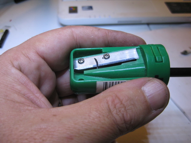
Tip: use a pencil sharpener to chamfer the ends of the air lines just a touch. A 1-2mm chamfer on the air line will allow it to slide through the o-rings and minimise risk of damaging the o-rings. A light smear of lube at the end of the air line also helps.
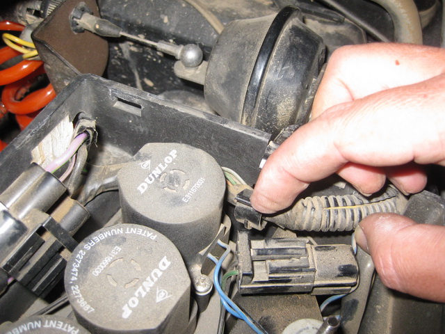
 Push the cable clips back in and secure the cables. Re-connect the wiring multi-plug to the valve block.
Replace the compressor, connect the multi-plug, and tighten the air line olive connector at the compressor side.
Tighten the nuts holding the compressor vibration mounts in place.
Mount the cruise control bracket and secure with the two screws removed at the beginning of this exercise.
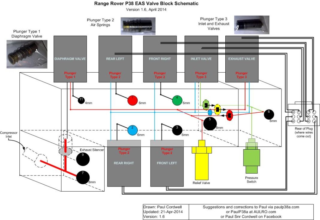
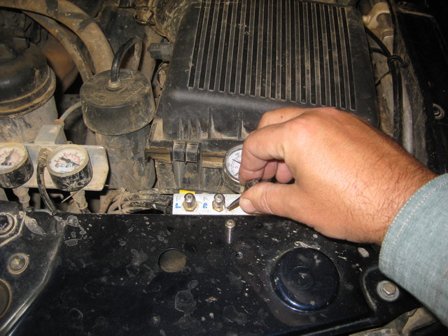
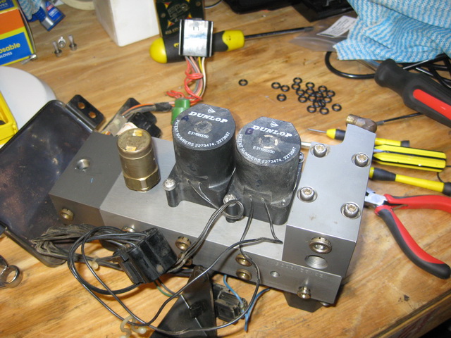
In case you were wondering, the orange curly hose and pressure gauge at the left of the photo above is an on-board air system that I use to inflate my tyres and/or clean the air filter. The pressure regulator keeps outgoing air pressure at less than 50psi and the 5m hose reaches all tyres.
Finally, we might as well replace the o-rings in the EAS Dryer, that’s the cylindrical unit between the Air Filter Box and the Power Steering Fluid Reservoir.
It is held in place by an 8mm bolt. Remove the air lines and collets, and replace the 2x 8mm o-rings at each end.
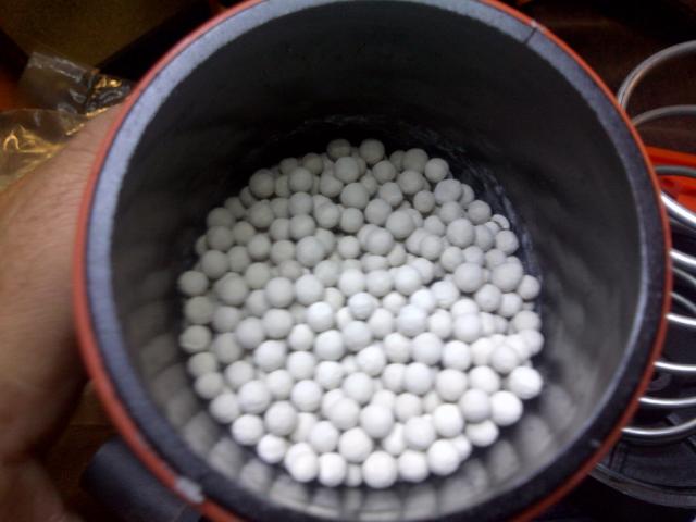
If you are curious about the state of the desiccant inside the dryer, the lid simply unscrews, but it is pretty tight due to the spring inside.
If you remove the mesh and filter gauze, you can see the desiccant. If yours is wet or powdery, it might be a good idea to get some new desiccant.
Reassemble the dryer, attached the bottom air line, secure it with the 8mm bolt and attached the top air line.
At this stage while the EAS is completely deflated, you might elect to replace the 6mm o-rings behind the collets on each air spring. The Hard Range O-ring Kit contains sufficient o-rings to do this although the procedure is not documented here.
That’s it as far as pulling stuff apart and reassembling is concerned.
Now would be a good time to double check that all air lines and wires are connected.
All that’s left to do now is pump up the system, leak test and replace the cover of the EAS housing.
Leak Testing
As a general guide with a standard air compressor, it should take about 7 to 8 minutes to inflate the system from empty to Standard EAS height. It should take a further 3 to 4 minutes before the EAS Compressor cuts out, indicating the pressure in the EAS Reservoir has reached more than 140-145psi.
With the compressor running, and adjusting the vehicle to different heights, spray all connections with soapy water and look for leaks indicated by bubbles on the connections.
If you find a leak, push/pull the air line connector and test again. If the leak persists, cut a couple of mm off the line to give a nice square-on connection. Remember to chamfer the end (1-2mm) on a freshly cut air line to minimise risk of damaging the o-rings.
To avoid flattening the battery, leave the engine running while doing these tests.
Rubbing and Vibration
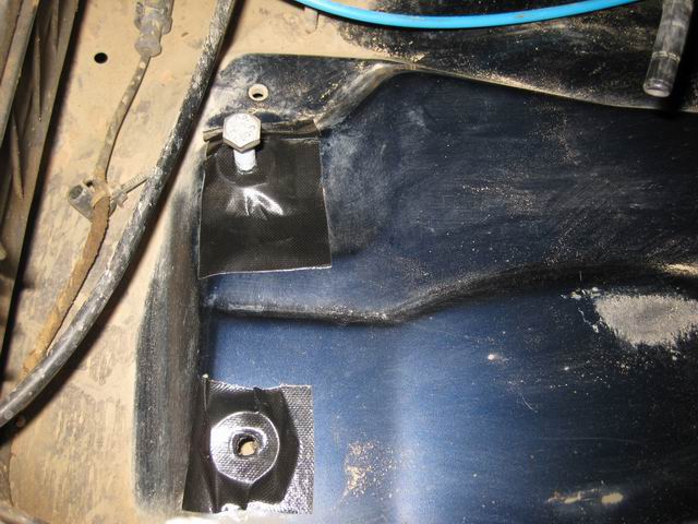
If you experience excessive cabin noise due to the air compressor operating, you might find that the EAS housing is rubbing on the body. You can see at the centre right of the picture below where the EAS housing was rubbing on the body of my 1999 P38.
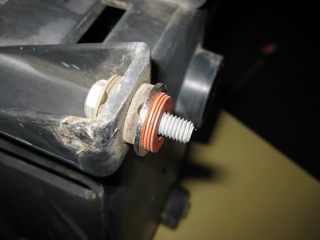
The housing can be lifted approx 5mm by inserting a metal machine washer and three fibre washers. To hold these in place, I put a dab of glue between each of the washers and then used some cloth tape to align them with the holes in the body.
The picture below shows the extra 5mm of lift afforded by the washers.
Follow-up
I recommend keeping an eye on it all for at least a week as the new components bed-in and I’d be checking the nuts and bolts to make sure they haven’t loosened up.
Best wishes for happy trails with your Rangie.
Cheers, Paul.